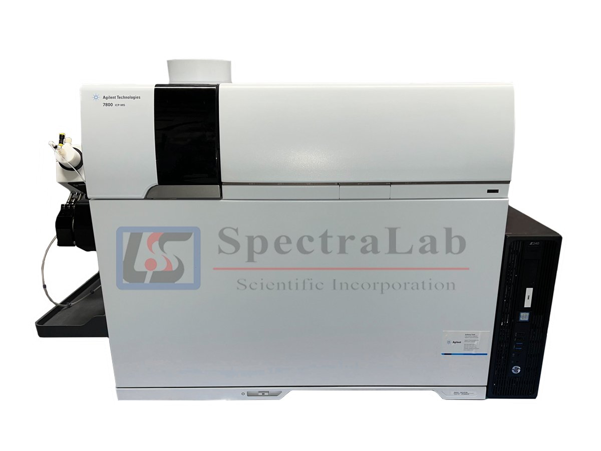
Technical Guide: Agilent ICP-MS Detector Systems
Overview of Agilent ICP-MS Detector Technology
You are working with sophisticated detector systems that form the analytical heart of Agilent ICP-MS instrumentation. The detector converts incident ions into measurable electrical signals through electron multiplication, enabling you to measure elemental concentrations spanning from parts-per-quadrillion (ppq) to percentage levels in a single analytical run.
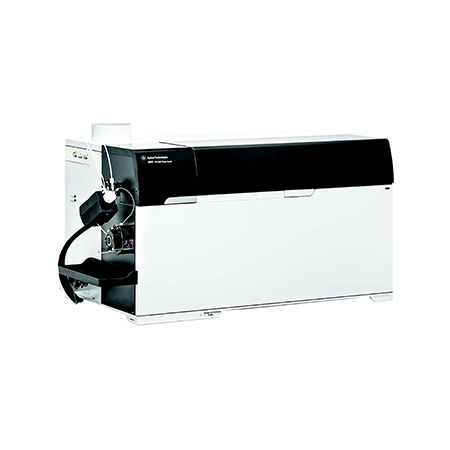
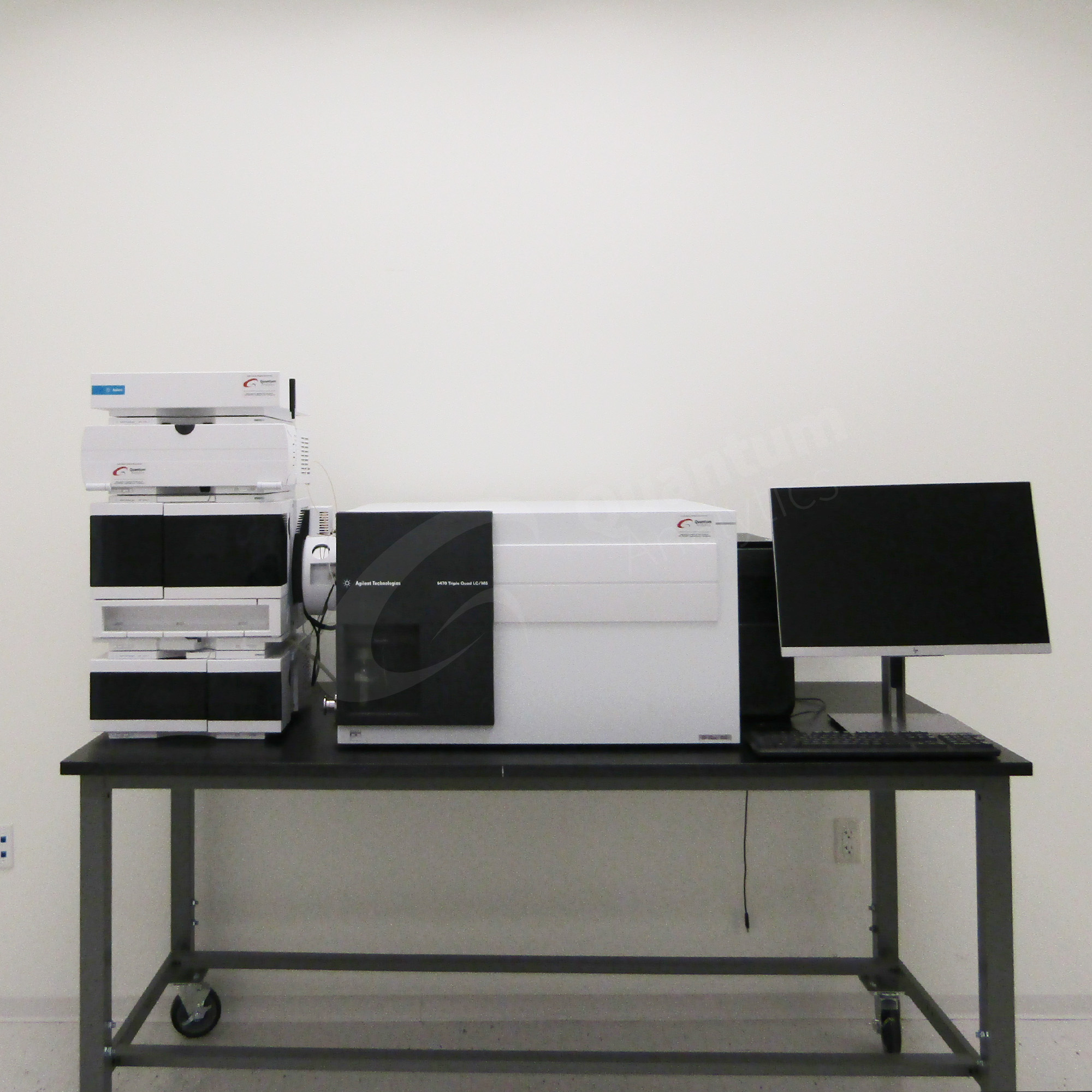
Agilent's detector technology has evolved significantly across the 7800 quadrupole, 8800 triple quadrupole, and 8900 triple quadrupole platforms. Each system employs electron multiplier technology optimized for specific analytical demands, from routine environmental testing to ultra-trace semiconductor analysis. Understanding your detector's capabilities and limitations is essential for achieving optimal analytical performance and maintaining instrument reliability over extended operational periods.
Technical Specifications Comparison
The following table presents critical performance parameters for the three primary Agilent ICP-MS detector configurations. You should reference these specifications when evaluating your instrument's capabilities and planning analytical methods:
Detector Design and Operational Principles
Electron Multiplier Detectors
Your Agilent ICP-MS employs an electron multiplier detector that operates through secondary electron emission cascade. When an ion strikes the detector's conversion dynode, it liberates multiple secondary electrons. These electrons are accelerated by an applied voltage gradient toward subsequent dynodes, where each impact generates additional secondary electrons. This cascade effect produces gains ranging from 10⁴ to 10⁸ electrons per incident ion, depending on your detector voltage settings.
Discrete Dynode Configuration
The 8900 ICP-MS systems utilize discrete dynode electron multipliers, which offer significant advantages over continuous dynode designs. You benefit from a larger active surface area—approximately 1000 mm² compared to 160 mm² for channel electron multipliers—which distributes the electron amplification workload across multiple dynodes. This design extends your detector's operational lifetime and provides superior gain stability, particularly important for long-term isotope ratio measurements.
Each discrete dynode in your system is fabricated from proprietary alloys with high secondary electron emission coefficients. The dynode chain typically contains 12 to 24 individual stages, with interstage voltages carefully optimized to maximize electron collection efficiency while minimizing noise. This configuration enables you to achieve detection limits in the sub-ppt range for many elements.
Orthogonal Detector System (ODS)
The 7800 ICP-MS features Agilent's Orthogonal Detector System, which positions the detector off-axis from the incident ion beam. This geometric arrangement deflects ions toward the detector while allowing photons and neutral particles to pass through undetected. You observe significant reductions in background noise, particularly at low masses where photon interference can compromise sensitivity. The ODS configuration contributes to the 7800's ability to deliver up to 11 orders of magnitude linear dynamic range.
Dual-Mode Operation: Pulse and Analog
Your detector operates in two distinct modes that automatically switch based on signal intensity. In pulse-counting mode, you measure individual ion arrivals as discrete pulses, optimized for signals below approximately 2 × 10⁶ counts per second (cps). This mode delivers maximum sensitivity for trace element detection.
When signal intensities exceed the pulse-counting threshold, your system automatically transitions to analog mode, measuring the continuous current generated by the electron multiplier. This dual-mode capability extends your linear dynamic range to 10-11 orders of magnitude, enabling you to quantify both trace and major elements without sample dilution or method modifications.
The transition between modes requires precise calibration of pulse-analog (P/A) factors. These multiplication factors align the two measurement scales to ensure seamless linearity across the entire dynamic range. You must optimize P/A factors regularly using multi-element calibration solutions to maintain quantitative accuracy.
Faraday Cup Detectors
While not standard equipment on single-collector Agilent ICP-MS systems, you may encounter Faraday cup detectors in multi-collector configurations or specialized applications. Faraday cups measure ion current directly without amplification, providing exceptional stability and freedom from mass discrimination effects. These detectors excel for high-precision isotope ratio measurements when beam intensities exceed approximately 200 mV, though they lack the sensitivity of electron multipliers for trace-level work.
Critical Performance Parameters
Detection Limits
You can achieve detection limits in the parts-per-quadrillion (ppq) range for many elements, particularly when operating in MS/MS mode on the 8800 or 8900 platforms. For example, thorium and uranium detection limits below 0.4 ppq have been demonstrated under optimized conditions. Your actual detection limits depend on multiple factors including matrix composition, interference levels, integration times, and detector condition.
Mass Resolution
Your quadrupole mass analyzer provides unit mass resolution of approximately 0.7 atomic mass units (amu) at full width half maximum. This resolution enables you to separate adjacent masses effectively for most applications, though you cannot resolve true isobaric interferences using mass resolution alone. For isobaric interference removal, you must employ MS/MS mode with appropriate reaction chemistry.
Abundance Sensitivity
Abundance sensitivity quantifies your instrument's ability to measure low-abundance isotopes adjacent to intense peaks. Standard quadrupole ICP-MS systems deliver abundance sensitivity values of approximately 10⁻⁷, meaning a signal at mass M+1 will be about one ten-millionth the intensity of a pure signal at mass M. Your 8800 and 8900 triple quadrupole systems achieve dramatically improved abundance sensitivity—theoretically up to 10⁻¹⁴ in MS/MS mode—because the tandem mass filtering eliminates peak tailing effects that limit single-quadrupole performance.
Detector Voltage Specifications
You should monitor your detector voltages during routine tuning to assess detector health. For pulse-counting mode, typical operating voltages range from 900 to 1800 V, with values exceeding 1800 V indicating approaching end-of-life. In analog mode, your detector may operate from 1500 to 3300 V, with replacement recommended when voltages exceed 3300 V. These voltage thresholds vary slightly between detector models; consult your specific instrument documentation for exact specifications.
Dead Time Correction
Your detector exhibits a characteristic dead time—typically 20 to 70 nanoseconds—during which it cannot register subsequent ion arrivals following detection of an ion. This dead time causes systematic count rate losses at high signal intensities, requiring mathematical correction for accurate quantification. You should verify your system's dead time setting periodically using isotope ratio measurements on certified reference materials such as the IRMM-072 series for uranium.
Dead time can be mass-dependent in some continuous dynode multipliers, decreasing with increasing mass number, though discrete dynode systems typically show mass-independent behavior. For high-accuracy isotope ratio work, you must validate dead time corrections across your analytical mass range.
Detector Optimization Procedures
Initial System Tuning
You should perform comprehensive detector optimization using a multi-element tuning solution, typically containing 1 ppb of elements spanning the mass range (e.g., Li, Y, Ce, Tl). Begin by running an electron multiplier tune (EM Tune) to establish baseline detector voltages and assess system sensitivity. Your tune report should show:
- Sensitivity >10,000 cps/ppb for mass 89 (Y) in no-gas mode
- Background counts <5 cps at mass 220
- CeO/Ce oxide ratio <2%
- Ce²⁺/Ce⁺ doubly-charged ratio <3%
If you cannot achieve these target values, investigate potential issues with your sample introduction system, ion optics, or vacuum system before proceeding with detector optimization.
Pulse-Analog Factor Calibration
After establishing baseline tune parameters, you must calibrate your P/A factors to ensure linear detector response across the dynamic range transition. Prepare a multi-element solution at concentrations that generate signals spanning the pulse-to-analog transition boundary—typically 100 to 300 ppb for most elements.
In your MassHunter or comparable software, access the Hardware Configuration panel and locate the detector settings. Initiate the P/A Factor acquisition routine, which will:
- Measure each selected isotope in both pulse and analog modes
- Calculate the ratio between analog and pulse responses
- Apply these factors to all subsequent measurements for seamless mode transitions
You should verify P/A factor accuracy by analyzing a linearity check solution spanning from sub-ppb to percentage levels. Plot your results on a log-log scale; correlation coefficients (R²) should exceed 0.9995 across the entire dynamic range. If you observe non-linearity, repeat the P/A calibration using fresh standards and verify your detector voltages remain within specification.
Independent P/A Factor Determination
For methods employing multiple tune modes (e.g., no-gas, helium collision, and reactive gas modes), you can enable Independent P/A Factor determination. This feature automatically measures and applies mode-specific P/A factors during batch analysis, compensating for differences in detector response characteristics under varying cell gas conditions. This approach eliminates the need for multiple calibration standards while ensuring optimal linearity across all operational modes.
Detector Gain Verification
You can assess your detector's gain stability by monitoring voltage requirements during routine tuning. A healthy detector should maintain stable voltages over weeks to months of operation. Rapid voltage increases—for example, a rise of 200-300 V within a few weeks—indicate accelerated detector aging and warrant closer monitoring. Document voltage trends in your maintenance log to predict replacement timing and avoid unexpected failures during critical analytical sequences.
Advanced Diagnostics and Troubleshooting
Low Sensitivity Diagnostics
When you encounter unexpectedly low sensitivity, follow this systematic diagnostic sequence:
-
Generate a tune report and compare sensitivity values to historical baselines. Focus on mass 89 (yttrium) as your primary sensitivity indicator.
-
Check detector voltages. If pulse high voltage exceeds 1800 V or analog high voltage exceeds 3300 V, your detector may be degraded and require replacement.
-
Verify signal stability by monitoring internal standard recovery throughout your analytical sequence. Instability >10% RSD suggests upstream problems rather than detector issues.
-
Examine background counts at masses 220 and 89. Elevated background (>50 cps) may indicate detector contamination or voltage-related noise.
-
Test with fresh tuning solution to eliminate the possibility of standard degradation.
If detector voltages remain within specification but sensitivity is consistently low, investigate your sample introduction system, ion lens alignment, and vacuum system integrity before concluding the detector has failed.
High Background Troubleshooting
You may occasionally observe elevated background counts that compromise detection limits. Diagnose high background issues through these steps:
-
Compare on-mass versus off-mass discrimination in your tune report. Large discrepancies suggest quadrupole discharge requiring service intervention.
-
Monitor mass 205 and 89 background counts. If mass 205 background exceeds five times that of mass 89, you likely have quadrupole discharge issues that require professional service.
-
Perform blank rinse monitoring by aspirating 2% nitric acid while monitoring analyte masses. Slowly decreasing backgrounds indicate contamination carryover rather than detector problems.
-
Inspect and clean interface cones. Remove sampling and skimmer cones, sonicate in 5% nitric acid for up to 6 hours, rinse with ultrapure water, and reinstall. This procedure often resolves chronic background issues.
-
Check for matrix interferences that may appear as background. Polyatomic species from residual argon, water, acids, or sample matrix can elevate apparent backgrounds at specific masses.
Precision and Stability Issues
Poor precision manifests as high relative standard deviation (RSD >5%) in replicate measurements. You should investigate:
-
Detector voltage fluctuations: Monitor detector voltage during extended analysis sequences. Variations indicate detector instability or inadequate temperature stabilization.
-
Peristaltic pump tubing condition: Worn tubing causes pulsation in sample delivery, appearing as precision problems. Replace tubing every 3-6 months under routine use.
-
Stabilization time: Increase pre-read stabilization delays to allow detector equilibration, particularly for the first measurement after rinse cycles.
-
Dead time correction accuracy: Verify your dead time setting using isotope ratio standards. Incorrect dead time produces systematic errors that worsen at higher count rates.
Detector Replacement Indicators
You should plan detector replacement when you observe:
- Pulse high voltage >1800 V despite optimization attempts
- Analog high voltage >3300 V
- Rapid voltage increases (>100 V/week) even with light use
- Unstable tune reports with sensitivity variations >20% day-to-day
- Increasing noise levels, particularly at higher voltages
- Inability to achieve target P/A factor linearity despite calibration
Typical detector lifetime ranges from 12 to 24 months, depending on sample matrix complexity, sample throughput, and operating conditions. You can extend detector life by minimizing exposure to high-intensity signals, particularly from argon and matrix components, and maintaining clean interface components to reduce ion-neutral collisions.
Safety Precautions and Warnings
High Voltage Hazards
DANGER: ELECTRIC SHOCK RISK
Your ICP-MS detector operates at voltages up to 3500 V, presenting serious electric shock hazards. You must observe these safety protocols:
-
Never attempt detector maintenance with power applied. Always shut down the instrument completely and verify power-off status before opening vacuum chamber access panels.
-
Respect all interlock systems. Your instrument features safety interlocks that prevent plasma operation when covers are removed. Never bypass or defeat interlock switches.
-
Allow proper discharge time. After powering down, wait at least 5 minutes before accessing high-voltage components to allow capacitor discharge.
-
Use insulated tools exclusively when working near high-voltage detector connections.
-
Verify grounding integrity before each maintenance session. Poor grounding increases shock risk and can damage sensitive electronics.
Plasma-Related Detector Hazards
Your detector operates in close proximity to the ICP torch, which generates:
-
Intense UV and RF radiation: The plasma produces ultraviolet light and radiofrequency energy at approximately 40 MHz and 1500 V RMS. Ensure all shielding is in place before plasma ignition.
-
Ozone and nitric oxide: Plasma operation generates these respiratory irritants. Verify adequate laboratory ventilation (minimum 4-6 room air changes per hour) and ensure your exhaust system is functioning properly.
-
Thermal hazards: The plasma operates at 6000-10,000 K. Although the detector is thermally isolated, adjacent components can reach elevated temperatures during extended operation.
Chemical Safety Considerations
You must protect your detector from chemical damage:
-
Avoid hydrofluoric acid (HF): HF rapidly damages detector components. If HF analysis is required, use specialized sample introduction hardware and flush systems thoroughly afterward.
-
Limit organic solvent exposure: High organic content (>2% v/v) can degrade detector performance and create explosion hazards in the plasma. Use appropriate safety interlocks and oxygen addition systems when analyzing organic samples.
-
Control total dissolved solids: Samples exceeding 0.2% TDS (without HMI/UHMI systems) deposit salts on interface cones, affecting detector background and sensitivity. You should dilute high-matrix samples or use matrix introduction accessories.
Personal Protective Equipment
You must wear appropriate PPE during detector maintenance:
- Safety glasses or face shield (required for all work near plasma or during maintenance)
- Chemical-resistant gloves (nitrile or neoprene) when handling cones or cleaning solutions
- Insulated gloves when accessing high-voltage areas after proper lockout/tagout
- Laboratory coat to protect against acid splashes
Emergency Procedures
In the event of detector-related emergencies:
-
Electric shock incident: Immediately disconnect power at the main breaker. Do not touch the victim until power is confirmed off. Administer first aid and summon emergency medical assistance.
-
Plasma ignition failure with gas flow: If the plasma fails to ignite but gas continues flowing, immediately press the emergency stop button and evacuate the area. Argon displaces oxygen and presents asphyxiation risks in poorly ventilated spaces.
-
Unusual detector noise or arcing: Shut down immediately using the emergency stop button. Do not attempt to restart until qualified service personnel have inspected the system.
-
Vacuum failure: A sudden vacuum loss can expose the detector to atmospheric pressure, potentially causing permanent damage. If vacuum alarms sound, shut down the plasma immediately and do not attempt detector voltage application until vacuum is restored to <10⁻⁵ torr.
You should conduct quarterly safety audits of all interlock systems, emergency stop functionality, and exhaust ventilation capacity to maintain a safe operating environment for high-voltage ICP-MS detector systems.
⚠️ Important: This guide summarizes safe repair practices based on industry best practices and manufacturer guidelines. Always consult the official manufacturer manual for model-specific procedures. Analytical instrument repair should only be performed by qualified personnel.
References
- 1. Agilent 7800 ICP-MS Product Page
- 2. Agilent 7800 ICP-MS Technical Brochure
- 3. Agilent ICP-MS Detectors Product Information
- 4. Agilent 8800 Triple Quadrupole ICP-MS Technical Overview
- 5. Agilent 8900 Triple Quadrupole ICP-MS Product Page
- 6. Agilent 8900 ICP-MS Technical Brochure
- 7. Dependence of Detector Dead Time on Analyte Mass Number in ICP-MS
- 8. Dead Time Correction for Isotope Ratio Mass Spectrometry
- 9. ICP-MS Dynamic Range Technical Flyer
- 10. The Importance of Routine Maintenance in ICP-MS - Spectroscopy Online
- 11. Agilent 7500 Series ICP-MS Hardware Manual
- 12. Agilent ICP-MS Safety and Regulatory Information
- 13. Practical Benefits of Abundance Sensitivity Using MS/MS ICP-MS
- 14. ICP-MS Analytical Aspects and Applications
- 15. Discrete Dynode Electron Multipliers in Mass Spectrometry
- 16. Agilent ICP-MS Interactive Troubleshooting Tool

